Overcenter valves (also called counterbalance valves) have great importance in hydraulic systems and have following key features:
These valves are used where there is vital importance in the system. They monitor the system and sense the pressure changes immediately. We can think of them as lifeguards! An overcenter valve can also be described as a pilot-assisted relief valve with an integral free flow check.
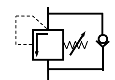
Overcenter valve hydraulic schema
Valve design can be inline type or cartridge type. They can be small but play an important role for safety in the applications.
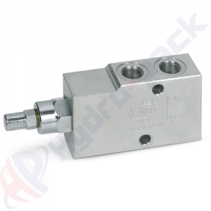
Inline type single overcenter valve
Overcenter valves are widely used on hydraulic motors in applications such as winches. While lowering, the load and gravity act in the same direction. This results in the load running away and a possible loss of control. Here the overcenter valve meters the flow out of the hydraulic motor to keep the load in place. The relief valve opens when the combined force created by the pilot pressure and the load-induced pressure exceeds the relief setting.

Relief setting of the overcenter valve and selection of pilot ratio (there are different pilot ratios 1:8, 1:4.5, 1:5.5, …) is important. In the case where the load varies drastically and sudden impact loads are expected, the relief pressure could be 20-30 % more than the load pressure. However, for horizontal cylinders, this could be as low as 5-10 %. The pilot pressure required to open the valve will depend on the pilot ratio that is the ratio between the relief area and the pilot area. The pilot pressure can be calculated as follows:
Valve setting = Load pressure + (Pilot pressure x pilot ratio)
Overcenter valves continually meter flow and controls descent. If the load begins to run away or shows signs of instability, the pressure in the pilot line will fall, causing the valve to restrict the flow exiting the actuator and preventing load runaway.
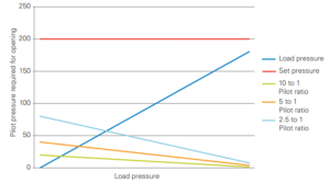
In general, higher pilot ratios work well for consistent, stable loads and lower pilot ratios for unstable or variable loads. In the chart below, you can see how a lower pilot ratio valve (2.5 to 1) has greater sensitivity to changes in the load pressure. In other words, if the load pressure suddenly increases, the operator will have to apply additional pilot pressure. Higher ratios will be more efficient (reduce heat generation) but at the cost of stability and smooth motion control. Typical example is extension of a straight boom.
Let’s calculate pilot pressure of a system where overcenter valve with a 3:1 pilot ratio adjusted for pressure setting 320 bar and with a load pressure 250 bar. In this case, the min. pilot pressure, required to open the relief valve is 23,33 bar.
320 = 250 + (Pilot pressure x 3)
However, in real systems, it is necessary to consider the actuator’s area ratio because the pressure what applied to pilot port 3 also applied to input of actuator and through actuator’s area difference – to port 1.
Valve setting = load pressure + [Pilot pressure x (pilot ratio+1/area ratio)]
320 = 250 + [Pilot pressure x (3 + 1/1.5)]
Pilot pressure is 19,12 bar.
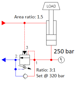
Please note that in the example above, overcenter valve is on the cap end of the cylinder with a load retracting the cylinder rod.
As a conclusion overcenter valves are critical components for safety and load control. It is not recommended to use them with closed center directional control valves. Neutral position of the valve spool should be floating center to reduce pilot pressure to “0” so that piston can reseat. But there are special overcenter valves that can be used with closed center directional control valves.
Pictures are used for educational purposes.
Sources